TM 1-1520-238-10
4-43
-90 DEG
+20 DEG
-45 DEG
120 DEG
+30 DEG
-60 DEG
+90 DEG
M01-102
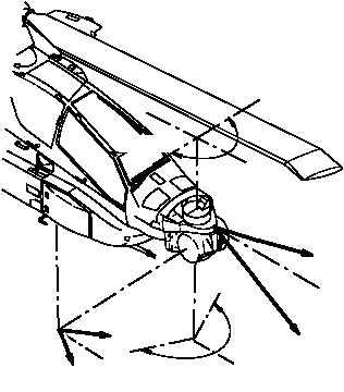
Figure 4-16.
TADS/PNVS Equipment Data
Table 4-14.
PNVS Equipment Data
Parameter
Function
Normal Azimuth Operating
Range
+90 degrees/
–90 degrees
Azimuth Stow Position
–118 degrees or greater
Elevation Operating
Range
+20 degrees/
–45 degrees
Field of View
30 degrees vertical/
40 degrees horizontal
Maximum Slew Rate
120 degrees per second
4.25.1 PNVS Electrical Power.
The PNVS receives
115 vac power from the No. 1 essential ac bus and 28 vdc
power from the No. 3 essential dc bus through the PNVS
AC and PNVS DC circuit breakers on the pilot overhead
circuit breaker panel. The PNVS is continuously moni-
tored by FD/LS which will illuminate the PNVS caution
light segment for a PNVS malfunction. The on command
DD/LS test (test 09-PNVS) will fault isolate to the LRU.
4.25.2 TADS Electronic Unit Failure.
In the event of a
TADS Electronic Unit (TADS computer) failure, the PNVS
will be placed in the direct mode automatically by the fire
control system. The PNVS turret will be directly driven by
the IHADSS sight electronics unit. PNVS turret motion
may be limited to 75 degrees left and 75 degrees right in
azimuth; turret motion may be erratic beyond the 75 de-
gree azimuth position. The message PNVS...DIRECT will
be displayed in the sight status block of the pilot’s high ac-
tion display. No corrective action is required by or avail-
able to the pilot.
4.25.3 Symbol Generator Failure.
In the event of a
symbol generator failure, the fire control system will auto-
matically command the IHADSS display electronics unit to
display PNVS FLIR 2 on the pilot/CPG HDU. The PNVS
will continue to function normally; however, the video dis-
played to the pilot will not have symbology. VDU video will
blank and the recorder will be inoperative. Additionally, the
CPG will receive TADS FLIR 2 video on the ORT. No cor-
rective action is required by or available to the pilot.
WARNING
If night or simulated night NOE, reaction
to the following malfunctions must be
immediate, exit of the NOE environment
may be required.
4.25.4 PNVS FLIR or Turret Failure.
In the event of a
failure of the PNVS FLIR or turret assembly, the pilot must
place the NVS switch on the collective switchbox (figs
2-11 and 2-12) in the TADS position. TADS will be slaved
to the pilot helmet LOS and moded to WFOV FLIR. Nor-
mally, this action will provide useable TADS video to the
pilot. However, in some cases, the TADS FLIR video may
be scrambled following loss of the PNVS FLIR video. If
this should occur, reselect PNVS on the pilot’s collective
NVS switch and then select TADS. The out-of-synch vid-
eo will be corrected. The slew rates of the TADS turret are
noticeably slower than those of the PNVS and some gain
and level adjustment may be required to obtain optimum
image quality.
4.25.5 IHADSS Failure.
In the event of an IHADSS fail-
ure, either inability to command the PNVS turret or loss of
video on the HDU, the pilot must first exit the NOE envi-
ronment. and then set the VDU control switch to PLT (fig
4-2) and the ACQ SEL switch to NVS FXD. This configu-
ration will allow the pilot to fly a fixed panel mounted dis-
play. Terrain flight capability will be directly dependent on
pilot proficiency.
4.26 WEAPONS SYMBOLOGY.
The weapons symbology is displayed to the CPG on the
video from the selected sight. The symbology is shown in
figure 4-17. Refer to table 4-15 for symbol definition.


