TM 1-1520-238-23
Change 8
1-332.1
1.110A. TAIL ROTOR BALANCE AVA KIT INSTALLATION – continued
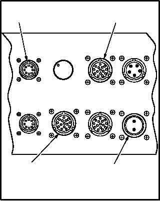
(5) Attach AH-64 to DAU cable terminations to
DAU receptacles labeled MULTI-CH (3), TA-
CHO 1 (4), and 28 VDC (5).
(6) Locate Control and Display Unit (CADU) in
CPG cockpit. Connect CADU to DAU cable
(29325601) to CADU and to DAU receptacle
labeled CADU (6).
1.110A.4. Optical RPM Sensor Installation
a. Install optical RPM sensor (7). Use
maintenance platform.
(1) Remove two airframe screws located on bot-
tom and in center of tail rotor gearbox fairing.
Retain screws for reinstallation.
(2) Mount optical RPM sensor mounting bracket
(8) on vertical stabilizer (9) with arrow on
bracket facing aft.
(3) Secure bracket (8) with screws PN
NAS603-10P. Ensure to provide a minumum
protrusion of two threads.
(4) Mount optical RPM sensor (7) on bracket (8).
NOTE
Cable will be routed to CPG station after
tail rotor accelerometer is installed.
(5) Route cable around and down vertical stabi-
lizer. Secure cable with clamps.
GO TO NEXT PAGE
TACHO
1
TACHO
2
MULTI-CH
TRACKER 1
28 VDC
TRACKER
MODE
CADU
STROBE
NIGHT
DA
Y
TEST
DATA ACQUISITION
UNIT
4
6
3
5
M04-5210-3
TAIL ROTOR OMITTED FOR
CLARITY
M04-5210-4
9
8
7


