TM 1-1520-238-23
1-332.2
Change 8
1.110A. TAIL ROTOR BALANCE AVA KIT INSTALLATION – continued
NOTE
If there is any unserviceable tape remain-
ing from previous balance routines, it
must be completely removed to ensure a
clean and accurate tachometer signal to
DAU.
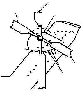
(6) Place a single, 4-inch strip of reflective tape
on either outboard blade, aligning the tape
with the approximate location of the 5-degree
beam from sensor. (Tape should be placed
with span of blade.)
NOTE
Blade with reflective tape will be referred
to in the AVA diagnostics as the #1 out-
board blade. Rotate blades in the direc-
tion of rotation and next blade is #1
inboard, and next blade is #2 outboard,
the next blade is #2 inboard.
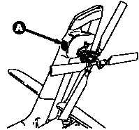
1.110A.5. Accelerometer Installation
a. Install accelerometer adapter bracket (11) on
tail rotor gearbox (12). Use maintenance
platform. Torque nut (13) to 150 INCH-POUNDS.
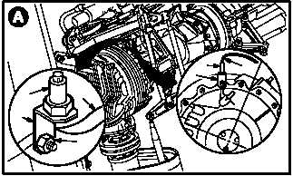
(1) Remove nut (13) from gearbox (12) at the
12:00 position.
(2) Install bracket (11) on gearbox (12) with nut
(3).
(3) Position bracket (11) so long axis of accel-
erometer (14) will be vertical.
(4) Torque nut (13) to 150 INCH-POUNDS. Use
torque wrench.
b. Inspect (QA).
c. Install accelerometer (14) on bracket (11).
d. Attach accelerometer cable connector (15) to
accelerometer (14).
GO TO NEXT PAGE
NO 1 INBOARD
REMOVE THESE TWO
SCREWS TO INSTALL OPTICAL
RPM SENSOR BRACKET
REPLACE REFLECTIVE
TAPE ON INSIDE
OF OUTBOARD
BLADE GRIP
NO 2 INBOARD
NO 2 OUTBOARD
TAILROTO
R
GEARBOX
NO 1 OUTBOARD
(TARGET
BLADE)
M04-5210-6
M04-5210-7
M04-5210-8
14
15
11
11
12
13
14