TM 1-1520-238-23
1-334
Change 8
1.111A. TAIL ROTOR BALANCE AVA KIT REMOVAL – continued
b. Detach accelerometer cable connector (3)
from accelerometer (4).
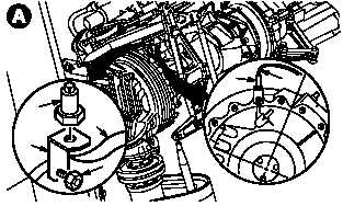
c. Remove accelerometer (4) from accelerome-
ter bracket (5).
d. Remove nut (6) and bracket (5) from tail rotor
gearbox (7).
e. Install nut (6) and torque to 150 INCH-
POUNDS. Use torque wrench.
f. Remove optical RPM sensor (8) from bracket
(9).
g. Remove bracket (9) from vertical stabilizer
(10).
h. Install screws previously removed.
i. Remove accelerometer and optical sensor
cables.
j. Enter CPG station (para 1.56). Observe all
safety precautions.
k. Detach DAU connectors.
(1) Detach TACHO 1 cable from DAU.
(2) Detach TACHO 2 cable from DAU.
(3) Detach ACC 4 cable from DAU.
(4) Detach connector from DAU receptacle la-
beled CADU.
(5) Detach MULTI-CH cable from DAU.
(6) Detach 28VDC cable from DAU.
l. Detach cable connector from CADU.
m. Remove DAU, CADU, and cable disconnected
from aircraft.
n. Disconnect SPU.
(1) Detach connector P4 (11) from SPU recep-
tacle J3 (12).
(2) Install protective cap on receptacle J3 (12).
GO TO NEXT PAGE
M04-5211-3
3
4
4
5
6
7
TAIL ROTOR OMITTED FOR
CLARITY
M04-5211-4
10
9
8
J1
J2
J3
M04-5211-5
11
12