TM 1-1520-238-23
3-182
Change 3
3.49.
TAIL LANDING GEAR WHEEL (WITHOUT GREASE FITTING) AND AXLE
REMOVAL/INSTALLATION – continued
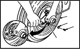
j. Adjust spacer (15).
(1) Rotate tire (19) by hand.
CAUTION
Do not tighten spacer until a heavy drag
is felt. Possible damage to wheel bear-
ings may occur.
(2) Tighten spacer (15) until bearings are firmly
seated and a slight drag in bearings can be
felt. Use spanner wrench set.
(3) Back off spacer (15) one full turn.
(4) Repeat step j.(2).
k. Install screw (17) in lock (16) and spacer (15).
(1) Aline holes in lock (16) with closest holes in
spacer (15).
(2) Install screw (17) and washer (18) in lock (16)
and spacer (15).
(3) Lockwire screw (17) to lock (16). Use wire
(item 224, App F).
l. Perform electrical bond check on cable
(TM 55-1500-323-24).
(1) Bond shall be 1.00 OHM or less. Use
multimeter.
m. Inspect (QA).
n. Service tail landing gear tire to 105 5 psi (para
1.44).
o. Remove tripod jack (para 1.69).
END OF TASK
M04-3429-7
19
17
16
15
18