TM 1-1520-238-23
2-296
Change 8
2.85.
LATERAL SERVOCYLINDER WIRE HARNESS SUPPORT BRACKET
REMOVAL/INSTALLATION – continued
2.85.6. Installation
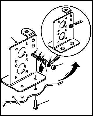
a. Install bracket (2) on transmission deck (20).
(1) Aline bracket (2) with transmission deck (20)
mounting holes.
(2) Install four rivets (21) (TM 1-1500-204-23).
b. Attach wire (16) to ground stud GS455 (17).
(1) Install washer (19), lock washer (19.1), nut
(18.1), wire (16) and lock nut (18) on ground
stud GS455 (17).
c. Perform
electrical
bond
check
(TM 55-1500-323-24).
(1) Bond shall be 2.5 MILLIOHM or less.
Use ohmmeter.
d. Apply sealing compound on ground stud as-
sembly (16), (17), (18), (18.1), (19), (19.1). Use
sealing compound (item 175, App F).
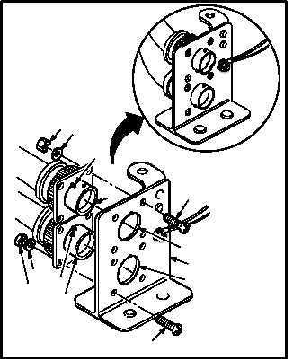
e. Install receptacle J415 (9) on bracket (2).
(1) Aline receptacle J415 (9) with bracket (2) bot-
tom mounting hole (22). Insert with key (23)
at twelve o’clock position.
(2) Install four screws (13), washers (14), and
nuts (15) on bracket (2) and receptacle J415
(9).
f. Install receptacle J225 (7) on bracket (2).
(1) Aline receptacle J225 (7) with bracket (2) top
mounting hole (24). Insert with key (25) at
twelve o’clock position.
(2) Install four screws (10), washers (11), and
nuts (12) on bracket (2) and receptacle J225
(7).
GO TO NEXT PAGE
M04-3596-6A
19
18
20
2
21
16
17
18.1
19.1
M04-3596-7
13
15
14
9
7
11
12
2
10
24
22
25
23