TM 1-1520-238-23
2-299
2.86.
ROTOR SUPPORT MIXER ASSEMBLY AND BOLT REMOVAL/INSTALLATION – continued
2.86.3. Removal
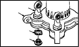
a. Remove mixer support bolt (1) from rotor sup-
port assembly (2).
(1) Clean sealing compound from mixer support
bolt (1), keyway washer (3), and shoulder of
mixer support fitting (4) (para 1.47).
(2) Pry back tabs of washer (3) from bolt (1).
b. Remove support (4) from base (2).
(1) Hold support (4). Remove bolt (1) and washer
(3) from base (2). Use torque wrench adapter.
(2) Discard washer (3).
2.86.4. Cleaning
a. Clean removed and attaching and parts and
surfaces (para 1.47).
2.86.5. Inspection
a. Check rotor support mixer assembly and
mounting surfaces for cracks and surface
corrosion. None allowed.
b. Check mixer support bolt for cracks and evi-
dence of damage. None allowed.
c. Check area where thread run-out intersects
thread relief.
(1) Thread run-out must not be below minimum
diameter of thread relief.
d. Check support for missing or damaged identi-
fication plate. None allowed.
e. Check bearing staking area for cracks and
damage. None allowed.
GO TO NEXT PAGE
2
3
1
M04-3306-2
M04-3306-3
1
3
2
4


