TM 1-1520-238-23
2-568
2.154.
CPG FIXED GLARESHIELD REMOVAL/INSTALLATION – continued
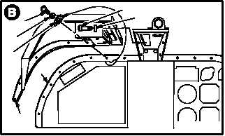
c. Remove CPG left glareshield (8) from panel
(2).
(1) Remove eight screws (9), washers (10), and
one electrical lead (11).
(2) Remove two screws (12) and washers (13).
(3) Remove left glareshield (8) from panel (2).
2.154.4. Cleaning
a. Wipe removed and attaching parts and sur-
faces with a clean rag.
2.154.5. Inspection
a. Check glareshield for cracks.
(1) Cracks up to 0.50 INCH are allowed. Cracks
over 0.50 INCH, replace glareshield.
b. Check glareshield mounting holes for
stripped threads (TM 1-1500-204-23).
2.154.6. Installation
NOTE
Install all screws and washers before
tightening.
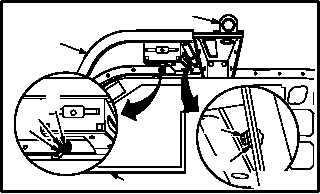
a. Install left glareshield (8) on panel (2).
(1) Aline left glareshield (8) with panel (2) and
boresight support (14).
NOTE
Electrical lead is installed on third screw
outboard of boresight support.
(2) Install eight screws (9), washers (10), and
electrical lead (11).
(3) Install two screws (12) and washers (13).
GO TO NEXT PAGE
9
10
11
8
12
13
2
M04-2109-3
9
2
M04-2109-7
14
8
11
12
13
10


