TM 1-1520-238-23
3-62
Change 6
3.18.
MAIN LANDING GEAR SHOCK STRUT REMOVAL/INSTALLATION – continued
3.18.3. Removal
NOTE
This task is typical for left and/or right
shock struts, except where noted.
The presence of hydraulic fluid at the
gas servicing port is a normal condi-
tion.
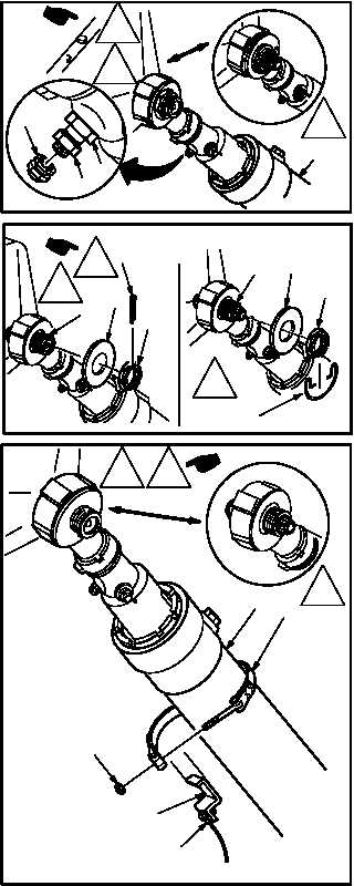
a. Deflate main landing gear shock strut (1).
(1) Remove valve cap (2) from shock strut air
valve (3).
(2) Turn outboard air valve nut (4) counterclock-
wise. Allow nitrogen pressure to bleed off.
b. Remove nut (5) and recessed washer (6) from
mount shaft (7).
(1) Remove and discard retaining ring (ADM) or
cotter pin (ADL)(ADN) (8).
(2) Remove nut (5) from shaft (7). Use socket
and hinged handle.
(3) Remove washer (6) from shaft (7).
c. Remove jumper (9) from shock strut (1).
(1) Remove sealant from clamp (10) and bracket
(11).
(2) Remove nut (12) from clamp (10).
(3) Remove clamp (10) from shock strut (1).
(4) Reposition jumper (9) and bracket (11) away
from shock strut (1).
d. Remove cable cutter (para 3.26).
GO TO NEXT PAGE
M04-053-2B
2
4
3
1
ADL
ADM
ADN
M04-053-3B
7
6
8
5
ADL
ADM
7
6
8
5
ADN
M04-053-10B
12
11
9
10
1
ADL
ADM
ADN


