TM 1-1520-238-23
3-64
Change 6
3.18.
MAIN LANDING GEAR SHOCK STRUT REMOVAL/INSTALLATION – continued
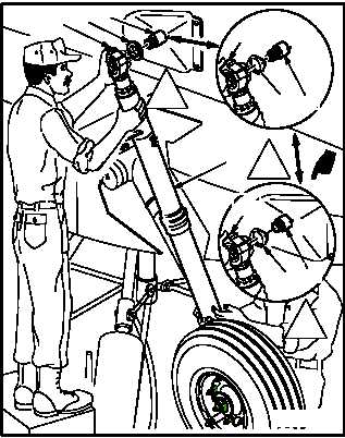
i. With one person holding shock strut (1) upper
end and second person lifting lower end, slide
shock strut upper rod end (21) off shaft (7).
(1) Guide strut (1) down and away from helicop-
ter.
j. Remove inboard washer (22) from shaft (7).
3.18.4. Cleaning
a. Wipe shock strut with a clean rag.
b. Clean jumper bonding area (para 1.47).
3.18.5. Inspection
a. Check shock strut piston for nicks, dents,
scratches, or cracks. None allowed.
b. Check shock strut main housing for nicks,
dents, and scratches.
(1) Maximum allowable depth 0.020 INCH. Blend
out any nicks, dents, or scratches
(TM 1-1500-204-23).
NOTE
Slight wetting of strut cylinder and seals
insufficient to form a drop is normal.
c. Check shock strut for leaks. None allowed.
NOTE
Squat switch and target are installed only
on left trailing arm.
d. Check squat switch and target for loose at-
tachment, loose electrical connections,
frayed wires, and cracks. None allowed.
GO TO NEXT PAGE
22
7
21
1
M04-053-9B
ADL
7
22
21
7
22
21
ADM
ADN


