TM 1-1520-238-23
Change 8
3-67
3.18.
MAIN LANDING GEAR SHOCK STRUT REMOVAL/INSTALLATION – continued
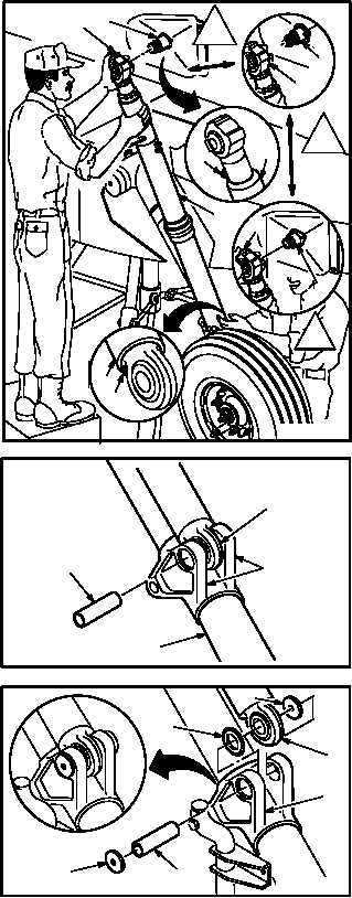
c. Guide shock strut (1) from under helicopter
up through opening in walkway.
d. Position shock strut (1) so filler valve (24) in
upper piston (25) is forward and facing down,
and drain plug (26) in lower piston (27) is fac-
ing down.
e. Slide strut upper rod end (21) on mount shaft
(7).
f. Check alinement of strut rod end (20) and lugs
(14).
(1) Position rod end (20) between lugs (14).
(2) Raise or lower trailing arm (18) with axle jack
until pin (17) can be inserted.
g. Install pin (17) through outboard lug (14),
washer (19), strut rod end (20), and inboard
lug (14).
h. Install trailing arm caps (13) on lugs (14).
i. Install cable cutter (para 3.26).
GO TO NEXT PAGE
7
21
1
M04-053-13B
7
21
24
25
27
26
ADM
ADL
7
21
ADN
M04-053-14
17
14
20
18
20
14
13
19
17
M04-053-15
13

