TM 1-1520-238-23
4-282
4.87.
LINK ASSEMBLY AFT ENGINE MOUNT REMOVAL/INSTALLATION – continued
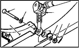
b. Remove aft link assembly (4) from nacelle (5).
(1) Remove and discard cotter pin (6) from bolt
(7).
(2) Hold bolt (7). Remove nut (8) and teflon
washer (9).
(3) Support link (4). Remove bolt (7) and washer
(10) from nacelle (5).
(4) Remove link (4).
4.87.4. Cleaning
a. Clean removed and attaching parts (para
1.47).
4.87.5. Inspection
a. Check engine support pins, heat shield, rod
assembly, link assembly, and aft lower engine
mount for cracks. None allowed.
b. Check removed and attaching parts for corro-
sion (para 1.49).
4.87.6. Repair
NOTE
Rod end and nut have left handed
threads.
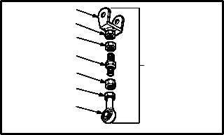
a. Remove and discard clevis (11) and/or rod
end (12).
(1) Remove lockwire from nut (13), turn buckle
(14), and nut (15).
(2) Hold clevis flat (16). Loosen nut (13).
(3) Remove clevis (11) and nut (13).
(4) Hold rod end flat (16). Loosen nut (15).
(5) Remove rod end (12) and nut (15).
GO TO NEXT PAGE
M04-3694-4
7
10
5
4
9
8
6
M04-3694-5
11
16
13
14
15
16
12
4


