TM 1-1520-238-23
4-285
4.87.
LINK ASSEMBLY AFT ENGINE MOUNT REMOVAL/INSTALLATION – continued
NOTE
Ensure clevis and rod end are alined
within 0 degrees to 30 degrees of each
other.
j. Torque nuts (13) and (15) to 35 INCH-POUNDS.
(1) Hold rod end flat (16). Torque nut (15) 35
INCH-POUNDS. Use torque wrench.
(2) Hold clevis flat (16). Torque nut (13) 35 INCH-
POUNDS. Use torque wrench.
k. Lockwire nut (13), turnbuckle (14), and nut
(15). Use wire (item 226, App F).
CAUTION
Torquing of bolt (7) will result in damage
to teflon washer (9).
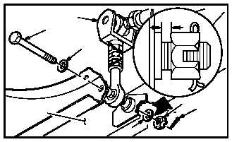
l. Install aft link assembly (4) in nacelle (5).
(1) Aline link (4) with holes in nacelle (5).
(2) Install bolt (7) through washer (10), nacelle
(5), and link assembly (4).
(3) Install teflon washer (9) and nut (8) on bolt
(7).
(4) Tighten nut (8) leaving 0.010 INCH gap be-
tween teflon washer (9) and nut (8).
(5) Install new cotter pin (6) in bolt (7).
GO TO NEXT PAGE
M04-3694-12
16
13
14
15
16
M04-3694-13
7
10
5
4
9
8
6
.010 IN


