TM 1-1520-238-23
4-283
4.87.
LINK ASSEMBLY AFT ENGINE MOUNT REMOVAL/INSTALLATION – continued
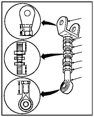
b. Install new clevis (11) and/or rod end (12).
(1) Install nut (13) 0.75 INCH on turnbuckle (14).
(2) Install nut (15) 0.75 INCH on turnbuckle (14).
(3) Install clevis (11) 0.50 INCH on turnbuckle
(14).
(4) Install rod end (12) 0.50 INCH on turnbuckle
(14).
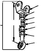
c. Adjust aft link assembly (4) to 3.77 INCHES
between clevis (11) and rod end (12).
(1) Measure distance from center of clevis (11)
hole to center of rod end (12) hole.
(2) Hold clevis (11) and rod end (12).
(3) Rotate turnbuckle (14) to adjust link assembly
to 3.77 INCHES.
4.87.7. Installation
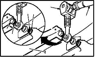
a. Install aft link assembly (4) in nacelle (5).
(1) Aline link (4) with holes in nacelle (5).
(2) Install bolt (7) through washer (10), nacelle
(5), and link assembly (4).
(3) Install teflon washer (9) and nut (8) on bolt
(7).
(4) Loosely install nut (8).
b. Position rod assembly (17) in clevis (4).
GO TO NEXT PAGE
M04-3694-6
0.50 IN
0.75 IN
0.50 IN
16
13
14
15
16
12
11
M04-3694-7
16
13
14
15
16
4
3.77 IN
11
12
4
17
M04-3694-8
10
8
9
7
5