TM 1-1520-238-23
4-570
Change 6
4.167.
PILOT POWER QUADRANT DISASSEMBLY/ASSEMBLY (AVIM) – continued
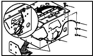
c. Install wire harness (73) and connector J1 (66)
in quadrant (2).
(1) Install screw (77) through quadrant (2),
ground wire end (76), and washer (75).
(2) Install locknut (74) on screw (77).
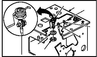
d. Install light indicating panel connector (67) in
quadrant (2).
(1) Position connector (67) in quadrant (2).
(2) Install washer (72) and nut (71) on connector
(67).
(3) Install screw (68) through washer (69) and
wire end (70) into connector (67).
CAUTION
To prevent damage to stop mechanism,
screws must be tightened evenly with no
excessive torque on any one screw.
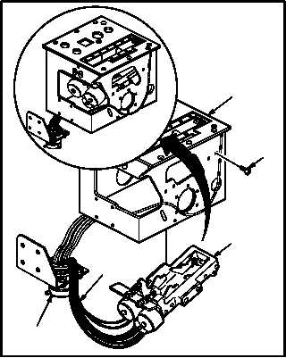
e. Install stop mechanism (57) in quadrant (2).
(1) Pin six identified wires (65) in connector J1
(66) (TM 55-1500-323-24).
(2) Position stop mechanism (57) in quadrant (2).
(3) Install four screws (64) through quadrant (2)
into stop mechanism (57).
GO TO NEXT PAGE
73
75
74
M04-3926-19
77
76
2
M04-3926-20
67
2
72
71
70
69
68
66
M04-3926-21
64
57
2
65