TM 1-1520-238-23
4-710
4.193.
PILOT POWER QUADRANT PANEL – NO. 1 ENGINE INTERLOCK SWITCH
REMOVAL/INSTALLATION (AVIM) – continued
4.193.3. Removal
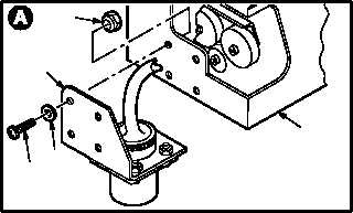
a. Remove bracket (1) from panel (2).
(1) Remove four screws (3), washers (4), and
locknuts (5).
(2) Remove lacing tape as required.
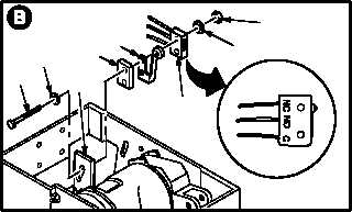
b. Remove interlock switch (6) from support
plate (7).
(1) Remove two nuts (8) and washers (9).
(2) Remove switch (6), switch actuator (10),
spacer (11), two washers (12), and screws
(13).
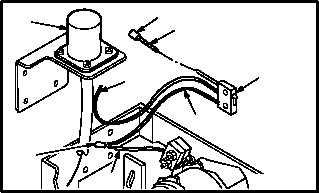
c. Detach wires (14) and (15).
(1) Identify and depin wire (14) from receptacle
J1 (16) (TM 55-1500-323-24).
(2) Identify and detach wires (15) and (17) from
wire cap (18) (TM 55-1500-323-24). Discard
wire cap (18).
(3) Do not remove wire cap (18) from wire (19) if
switch is being removed for other mainte-
nance.
GO TO NEXT PAGE
M04-3330-2
5
1
4
3
2
M04-3330-3
11
9
13
12
7
10
8
6
16
18
19
14
17
M04-3330-4
15
18
6


