TM 1-1520-238-23
4-712
4.193.
PILOT POWER QUADRANT PANEL – NO. 1 ENGINE INTERLOCK SWITCH
REMOVAL/INSTALLATION (AVIM) – continued
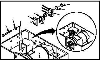
b. Install switch (6) on support plate (7).
(1) Install two screws (13) through washers (12),
plate (7), spacer (11), switch actuator (10),
and switch (6).
(2) Apply sealing compound to threads of two
screws (13). Use sealing compound
(item 172, App F).
(3) Install two washers (9) and nuts (8). Do not
tighten.
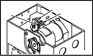
CAUTION
To prevent damage to switch, ensure
switch actuator does not bend excessive-
ly during switch closure, and that switch
opens past the IDLE position.
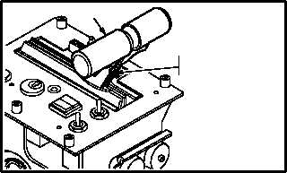
c. Adjust switch (6).
NOTE
Switch will actuate only when No. 1 en-
gine power lever is between OFF and
IDLE.
(1) Set No. 1 engine power lever (21) to IDLE.
(2) Adjust switch (6) so switch actuator (10)
presses plunger (22) to its maximum travel.
(3) Set lever (21) to idle, ensure switch (6) is in
open position.
d. Tighten two nuts (8).
e. Install lacing tape as required. Use tape
(item 202, App F).
GO TO NEXT PAGE
M04-3330-6
11
9
13
12
10
8
6
7
M04-3330-7
THROTTLE LEVERS
IN •IDLE" POSITION
21
M04-3330-8
22
10
6