TM 1-1520-238-23
5-82
Change 1
5.15.
MAIN ROTOR BLADE ELECTROSTATIC DISCHARGER DISASSEMBLY/ASSEMBLY – continued
5.15.4. Cleaning
a. Clean electrostatic discharger, stud, fitting,
and brackets. Use methyl ethyl ketone
(item 124, App F) (para 1.47).
CAUTION
To prevent damage to main rotor blade,
sand metallic surfaces in a spanwise di-
rection and sand glass skin surfaces in a
chordwise direction.
NOTE
Perform steps b and c only if one or
both brackets were removed. Other-
wise, proceed directly to paragraph
5.15.5.
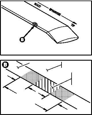
The bracket bonding area on the blade
trailing edge consists of the bracket
mating surface and an area extending
a minimum of 4 inches beyond the in-
board and outboard sides of bracket
mating surface.
b. Remove top coat of paint and primer from
bracket bonding area.
(1) Sand bracket bonding area in a spanwise di-
rection.
(a) Start with cloth (item 47, App F).
(b) Finish with cloth (item 48, App F).
(2) Verify that no traces of paint remain on brack-
et bonding area.
GO TO NEXT PAGE
M04-2308-6
M04-2308-7
MAIN ROTOR
BLADE SURFACE
DISCHARGE
BRACKET
BONDING AREA
4 IN
4 IN
DISCHARGE
BRACKET
MATING
SURFACE
TRAILING EDGE