TM 1-1520-238-23
6-544
Change 4
6.131.
INTERMEDIATE GEARBOX REMOVAL/INSTALLATION – continued
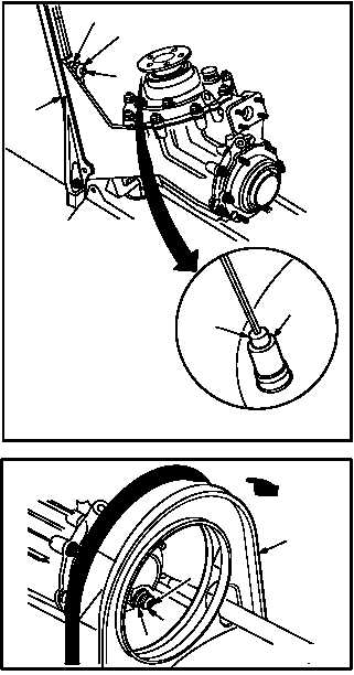
(7) Apply corrosion preventive compound to four
nuts (10), washers (11), and exposed threads
on studs (12). Use corrosion preventive
compound (item 62, App F).
(8) Attach connector P59 (8) to accelerometer
receptacle J1 (9).
(9) Apply a bead of sealant around each gearbox
mounting foot at mating point on stabilizer (7).
Use sealing compound (item 177, App F).
b. Install diffuser (1) on four studs (5). Torque four
nuts (3) to 60 INCH-POUNDS.
(1) Slide diffuser (1) aft until four studs (5) are
engaged.
(2) Install four washers (4) and nuts (3) on studs
(5).
(3) Torque four nuts (3) to 60 INCH-POUNDS.
Use torque wrench.
c. Inspect (QA).
d. Install directional F.S. 520 bellcrank (para
11.267).
e. Install intermediate gearbox input coupling
(para 6.12).
f. Install No. 5 tail rotor drive shaft, damper, and
antiflail (para 6.11).
g. Install intermediate gearbox output coupling
(para 6.13).
h. Install No. 6 tail rotor drive shaft (para 6.14).
i. Install intermediate gearbox temperature sen-
sors (top forward, top aft, and right side) (para
6.130).
j. Install access fairings R475, L510, and R510
(para 2.2).
k. Perform drive system dynamic maintenance
operational check (TM 1-1520-238-T).
END OF TASK
M04-555-2
10
11
12
7
9
8
M04-555-8A
5
4
3
1