TM 1-1520-238-23
7-178
Change 5
7.45.
LATERAL SERVOCYLINDER INSTALLATION – continued
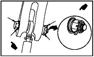
h. Install nut (15) on bolt (14). Torque nut (15) 900
to 1100 INCH-POUNDS.
(1) Hold bolt (14). Use open end wrench.
(2) Install nut (15).
(3) Torque nut (15) to 900 INCH-POUNDS. Use
socket and torque wrench.
(4) Increase torque to aline cotter pin hole, but do
not exceed 1100 INCH-POUNDS.
(5) Install new cotter pin (16).
(6) Apply sealing compound around bolt (14)
head, washer(s) (14.1), and nut (15). Use
sealing compound (item 176, App F).
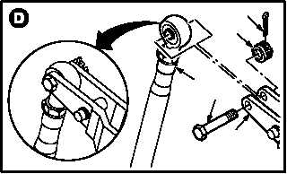
i. Install rod end (17) on control arm (18). Torque
nut (20) 30 to 40 INCH-POUNDS.
(1) Install bolt (19) through arm (18) and rod end
(17).
(2) Check fit of self-retaining bolt (19) (para
11.1).
(3) Install nut (20).
(4) Hold bolt (19). Torque nut (20) to 30 INCH-
POUNDS. Use torque wrench.
(5) Increase torque to aline cotter pin hole, but do
not exceed 40 INCH-POUNDS.
(6) Install new cotter pin (21).
GO TO NEXT PAGE
M04-810-5A
14
16
15
VIEW
ROTATED
14.1
21
20
19
18
M04-810-10
17