TM 1-1520-238-23
7-180
7.45.
LATERAL SERVOCYLINDER INSTALLATION – continued
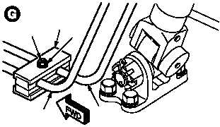
m. Install tube clamp (31). Torque screw (32) to 23
INCH-POUNDS.
(1) Install halves of tube clamp (31) over tubes
(22) and (25). Aline mounting holes.
(2) Install screw (32) and washer (33).
(3) Torque screw (32) to 23 INCH-POUNDS. Use
torque wrench.
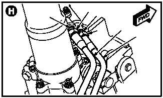
n. Install utility return tube (34) on adapter (35).
(1) Lubricate threads on adapter (35). Use clean
hydraulic fluid (item 92, App F).
(2) Install nut (36).
o. Install utility pressure tube (37) on adapter
(38).
(1) Lubricate threads on adapter (38). Use clean
hydraulic fluid (item 92, App F).
(2) Install nut (39).
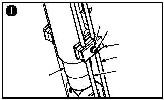
p. Install tube clamp (40). Torque screw (41) to 23
INCH-POUNDS.
(1) Position half of clamp (40) between servocy-
linder (3) and tubes (34) and (37).
(2) Position other half of clamp (40) over tubes
(34) and (37). Aline mounting hole.
(3) Install screw (41) through washer (42) and
clamp (40).
(4) Torque screw (41) to 23 INCH-POUNDS. Use
hexagon screwdriver and torque wrench.
GO TO NEXT PAGE
M04-810-11
32
31
33
25
22
M04-810-8
35
3638
39
37
34
42
40
41
37
34
3
M04-810-9