TM 1-1520-238-23
7-182
Change 8
7.45.
LATERAL SERVOCYLINDER INSTALLATION – continued
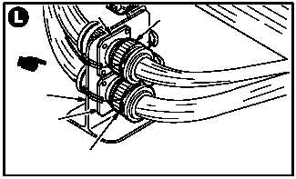
u. Attach connector (L35)P225 (50) to receptacle
J225 (51).
v. Attach connector (L35)P415 (52) to receptacle
J415 (53).
CAUTION
Ensure lockwire does not pre-load plug
side of connector in either direction. En-
sure anti-chafe tubing is positioned so
that no chafing between lockwire and
connector bracket occurs.
w. Lockwire connector P225 (50) to connector
P225 (50).
(1) Install safety wire with nonmetallic tubing
(anti-chafe), from the barrel of the connector
P225 (50), then around connector bracket
(53.1) and attach safety wire to the barrel of
connector P225 (50). Use wire (item 222,
App F) and tubing (item 213A, App F).
x. Lockwire connector P415 (52) to connector
P415 (52).
(1) Install safety wire with nonmetallic tubing
(anti-chafe), from the barrel of the connector
P415 (52), then around connector bracket
(53.1) and attach safety wire to the barrel of
connector P415 (52). Use wire (item 222,
App F) and tubing (item 213A, App F).
y. Inspect (QA).
z. Bleed primary and utility hydraulic systems
(para 1.35).
aa. Service primary and utility hydraulic systems
(para 1.34).
ab. Perform lateral (cyclic) flight control rigging
maintenance
operational
check
(TM 1-1520-238-T).
ac. Perform linear variable differential transducer
(LVDT) adjustment (para 11.216).
ad. Perform primary and utility systems mainte-
nance operational checks (TM 1-1520-238-T).
ae. Install access panel L200 and fairing T205L
(para 2.2).
END OF TASK
M04-810-15A
53
52
50
51
53.1