TM 1-1520-238-23
8-119
8.46.
PILOT/CPG CLOCK REMOVAL/INSTALLATION – continued
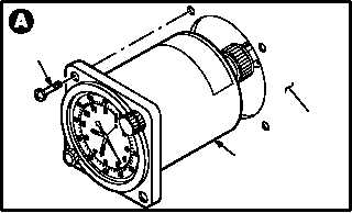
c. Remove clock (1) from instrument panel (2).
(1) Remove two screws (3).
(2) Pull clock (1) from panel (2).
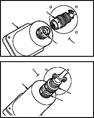
(3) Detach connector P121 (pilot)/P127 (CPG)
(4) from receptacle (M21)J1 (pilot)/(M49)J1
(CPG) (5).
8.46.4. Cleaning
a. Wipe mounting area and clock with a clean
rag.
8.46.5. Inspection
a. Check clock and panel mounting area for
cracks, nicks, and dents (para 8.43).
b. Check panel screw holes for stripped or dam-
aged threads (para 8.43).
8.46.6. Installation
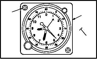
a. Install clock (1) in panel (2).
(1) Attach connector P121 (pilot)/P127 (CPG) (4)
to receptacle (M21)J1 (pilot)/(M49)J1 (CPG)
(5).
(2) Aline clock (1) with screw holes in panel (2).
(3) Install two screws (3).
b. Inspect (QA).
c. Perform miscellaneous instruments mainte-
nance operational check (TM 1-1520-238-T).
END OF TASK
M04-193-3
3
1
2
5
M04-193-4
1
4
2
4
1
2
5
M04-193-5
PUSH HARD
M04-193-6
3
1
2