TM 1-1520-238-23
Change 1 9-15
9.3.
PILOT CIRCUIT BREAKER PANEL INSTALLATION
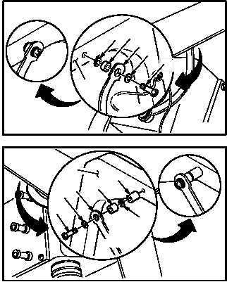
c. Install aft hinge strap (4) on pilot station struc-
ture (5).
(1) Install screw (6) through washer (7), strap (4),
spacer (8), and washer (7) in structure (5).
d. Install forward hinge strap (9) on pilot station
structure (10).
(1) Install screw (11) through washer (12), strap
(9), spacer (13), washer (12), and spacer (14)
in structure (10).
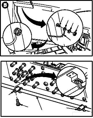
e. Install circuit breaker panel bonding strap (15)
on stud (16).
(1) Position terminal lug (17) on stud (16).
(2) Install washer (18) and nut (19) on stud (16).
(3) Perform
electrical
bond
check
(TM 55-1500-323-24).
(a) Bond shall be 0.1 OHM or less. Use
ohmmeter.
(4) Apply sealing compound. Use sealing
compound (item 163, App F).
f. Install defog hose (20) on panel (1).
(1) Position two clamps (21) on panel (1).
(2) Install two screws (22) through clamps (21) in
panel (1).
GO TO NEXT PAGE
M04-1408-17
5
8
4
7
6
VIEW
ROTATED
7
M04-1408-16
11
129
13
12
14
10
VIEW
ROTATED
M04-1408-13
1617
1819
15
VIEW
ROTATED
21
22
20
21
M04-1408-18
VIEW
ROTATED
1