TM 1-1520-238-23
9-11
9.2.
PILOT CIRCUIT BREAKER PANEL REMOVAL
9.2.1. Description
This task covers:
Removal. Cleaning. Inspection.
9.2.2. Initial Setup
Tools:
Electrical tool kit (item 378, App H)
L-style socket head key set (item 187, App H)
3-piece spatula set (item 337, App H)
Personnel Required:
68X
Armament/Electrical System Repairer
Equipment Conditions:
Ref
Condition
1.57
Helicopter safed
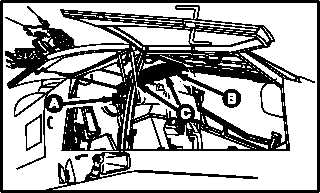
9.2.3. Removal
a. Enter pilot station (para 1.56). Observe all
safety precautions.
b. On pilot aft circuit breaker panel, open six
POWER circuit breakers.
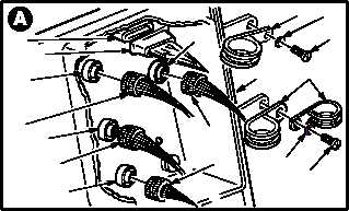
c. Detach five connectors from power distribu-
tion box (1).
(1) Detach connector P1 (2) from receptacle
(A402)J1 (3).
(2) Detach connector P2 (4) from receptacle
(A402)J2 (5).
(3) Detach connector P3 (6) from receptacle
(A402)J3 (7).
(4) Detach connector P4 (8) from receptacle
(A402)J4 (9).
(5) Detach connector P5 (10) from receptacle
(A402)J29 (11). Use socket head key set.
d. Remove three harness clamps (12).
(1) Remove two screws (13) and washers (14)
from three clamps (12).
(2) Remove three clamps (12).
GO TO NEXT PAGE
M04-1407-1
1
3
10
7
5
6
12
M04-1407-12
14
12
14
13
2
4
11
9
13
8