TM 1-1520-238-23
9-17
9.4.
PILOT CIRCUIT BREAKER LIGHT INDICATING PANEL REMOVAL/INSTALLATION
9.4.1. Description
This task covers:
Removal. Cleaning. Inspection. Installation.
9.4.2. Initial Setup
Tools:
Electrical tool kit (item 378, App H)
Personnel Required:
68X
Armament/Electrical System Repairer
68X3F
Armament/Electrical System Repairer/
Technical Inspector
References:
TM 1-1520-238-T
Equipment Conditions:
Ref
Condition
1.57
Helicopter safed
NOTE
This task is typical for each pilot circuit
breaker panel.
9.4.3. Removal
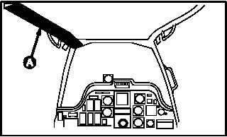
a. Enter pilot station (para 1.56). Observe all
safety precautions.
b. On pilot center circuit breaker panel, open LT
PRI circuit breaker.
NOTE
The following step refers to circuit break-
ers with a plastic knob. The aft panel has
2 knobs; the center panel has 12 knobs.
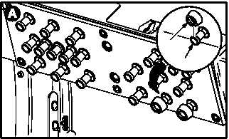
c. Remove plastic knob (1) from circuit breaker
(2).
(1) Open circuit breaker (2).
(2) Remove knob (1) at slotted opening.
(3) Close circuit breaker (2).
GO TO NEXT PAGE
M04-1317-1
PILOT STATION
M04-1317-4
2
1