TM 1-1520-238-23
Change 7 9-14.1/(9-14.2 blank)
9.3.
PILOT CIRCUIT BREAKER PANEL INSTALLATION
9.3.1. Description
This task covers:
Installation.
9.3.2. Initial Setup
Tools:
Electrical tool kit (item 378, App H)
L-style socket head key set (item 187, App H)
Ohmmeter (item 218, App H)
Materials/Parts:
Sealing compound (item 163, App F)
Personnel Required:
68X
Armament/Electrical System Repairer
68X3F
Armament/Electrical System Repairer/
Technical Inspector
References:
TM 1-1520-238-T
TM 55-1500-323-24
Equipment Conditions:
Ref
Condition
1.57
Helicopter safed
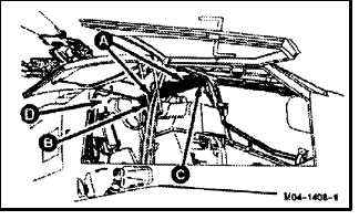
9.3.3. Installation
a. Enter pilot station (para 1.56). Observe all
safety precautions.
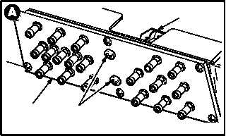
CAUTION
To prevent damage to transparent barrier
or pilot glareshield, install two screws in
forward end of panel first, then support aft
end of panel while installing remaining
two screws.
b. Install pilot circuit breaker panel (1) on mount-
ing brackets (2).
(1) Position panel (1) on mounts (2).
(2) Install two screws (3) in forward end of panel
(1).
(3) Install two screws (3) in aft end of panel (1).
GO TO NEXT PAGE
2
1
3
M04-1408-12