TM 1-1520-238-23
9-24
9.6.
PILOT CIRCUIT BREAKER PANEL EDGE LT PNL ON/OFF SWITCH REPLACEMENT – continued
9.6.6. Installation
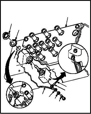
a. Install new switch (9) on panel (2).
(1) Install lockring (15) on switch (9).
(2) Position switch (9) so that tab (16) on lockring
(15) seats in locator hole (17).
(3) Install nut (13) and washer (14).
b. Attach identified wires (8) to switch S1 (9).
(1) Install two screws (10) through washers (11)
and four lugs (12) in circuit breaker (9).
c. Inspect (QA).
d. Install cover (1) on panel (2).
(1) Position cover (1) over stud (5).
(2) Install washer (4) and nut (3) on stud (5).
(3) Install three screws (6) and washers (7).
e. Install pilot circuit breaker panel (para 9.3).
f. Perform circuit breaker panel edge-lights
maintenance
operational
check
(TM 1-1520-238-T).
END OF TASK
8
1211
10
VIEW
ROTATED
16
M04-1314-5
13
14
15
2
17
9
8
12
3
4
5
7
6
2
M04-1314-12
VIEW
ROTATED
1