TM 1-1520-238-23
9-26
9.7.
PILOT CIRCUIT BREAKERS (NOT ATTACHED TO BUS BARS) REPLACEMENT – continued
NOTE
Forward and aft panels have six screws
each. The center panel has five screws.
b. Remove light indicating panel (3) from pilot
circuit breaker panel (4).
(1) Remove screws (5).
(2) Remove panel (3).
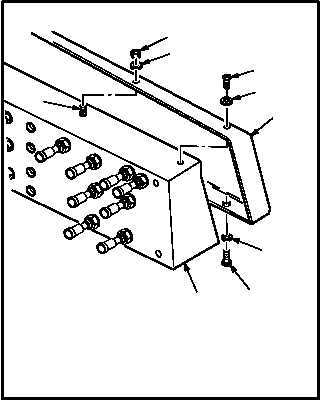
c. Remove back cover (6) from panel (4).
(1) Remove nuts (7) and washers (8) from studs
(9).
(2) Remove screws (10) and washers (11) as
required.
(3) Remove cover (6).
d. Detach wires (12) from circuit breaker (2).
(1) Identify wires (12) attached to circuit breaker
(2).
(2) Remove screws (13), washers (14), and ter-
minal lugs (15).
e. Remove circuit breaker (2) from panel (4).
(1) Remove nut (16) and washer (17).
(2) Remove and discard circuit breaker (2).
GO TO NEXT PAGE
4
3
5
M04-1819-4
7
8
9
6
10
11
M04-1819-12
10
11
4
16
4
17
13
14
15
2
12
M04-1819-5
12