TM 1-1520-238-23
9-51
9.14.
GENERATOR CONTROL UNIT (GCU) NO. 1 OR NO. 2 REMOVAL/INSTALLATION
9.14.1. Description
This task covers:
Removal. Cleaning. Inspection. Installation.
9.14.2. Initial Setup
Tools:
Electrical tool kit (item 378, App H)
Ohmmeter (item 218, App H)
Personnel Required:
68X
Armament/Electrical System Repairer
68X3F
Armament/Electrical System Repairer/
Technical Inspector
References:
TM 1-1520-238-T
TM 55-1500-323-24
Equipment Conditions:
Ref
Condition
1.57
Helicopter safed
9.9
Electrical power distribution box cover re-
moved
NOTE
This task is typical for either generator
control unit. The A1 generator control unit
is on the left side of the electrical power
distribution box. The A2 generator control
unit is on the right.
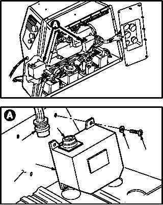
9.14.3. Removal
a. Enter pilot station (para 1.56). Observe all
safety precautions.
b. Remove generator control unit (1) from elec-
trical power distribution box (2).
(1) Detach connector P1 or P7 (3) from recep-
tacle J1 (4).
(2) Remove four screws (5) and washers (6)
from control unit (1).
(3) Remove control unit (1).
GO TO NEXT PAGE
M04-1093-1
4
3
1
6
M04-1093-3
5
2