TM 1-1520-238-23
9-146
Change 1
9.41.
BATTERY RELAY REMOVAL/INSTALLATION – continued
CAUTION
Ensure diode band (gate) is alined to X1
for proper polarity during installation. Ac-
cidental polarity reversal will damage
diode and/or other components.
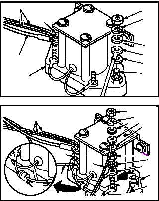
c. Attach identified wires (1) and diode (2) to
relay (3).
(1) Install two flat washers (17), terminal lugs
(16), flat washers (15), lockwashers (14), and
nuts (13) on terminal studs (18) and (19).
(2) Install identified diode (2), two terminal lugs
(10.1), lockwashers (10), nuts (9), flat wash-
ers (8), terminal lugs (7), flat washers (6),
lockwashers (5), and nuts (4) on terminal
studs (11) and (12).
(3) Spray corrosion preventive film on terminal
stack-ups on studs (11), (12), (18), and (19).
Use corrosion preventive compound
(item 64, App F).
(4) Apply corrosion preventive compound to ter-
minal stack-ups on studs (11), (12), (18), and
(19). Use corrosion preventive compound
(item 62, App F).
d. Install helicopter battery (para 9.40).
e. Inspect (QA).
f. Perform battery maintenance operational
check (TM 1–1520–238–T).
GO TO NEXT PAGE
1
1
3
18
13
14
15
16
17
19
M04-1135-7
1
10.1
9
10
12
1
11
1
45
6
7
8
3
1
2
M04-1135-8A


