TM 1-1520-238-23
Change 2
10-571
10.135.
FUEL QUANTITY INDICATOR TEST (TF 579) SET INSTALLATION/REMOVAL – continued
(6) Inspect (QA).
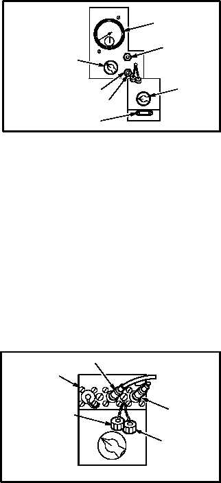
(7) Set FUNCTION SELECTOR switch (9) to
CAP IND HIGH CAL.
(8) Set RANGE SELECTOR switch (10) to X50.
NOTE
Nameplate capacitance value must be di-
vided by 50 then compared to indicated
value.
(9) Check that CAPACITANCE INDICATOR (11)
reads value stamped on STANDARD CA-
PACITOR MMF NAMEPLATE (14) divided
by 50. If not, remove protective cap from
HIGH ADJ control (15), and adjust control
screw (16) until reading is exactly equal to
nameplate value divided by 50.
(10) Repeat substeps (2) through (9) as often as is
necessary to obtain proper readings.
(11) Inspect (QA).
(12) Install protective caps on ZERO ADJ control
(12) and HIGH ADJ control (15).
(13) Set FUNCTION SELECTOR switch (9) to
CAP IND ZERO CAL.
(14) Set RANGE SELECTOR switch (10) to X1.
b. Check harness adapter lead capacitance.
(1) On indicator test set (6), remove test set pro-
tective caps from TANK UNIT COAX A recep-
tacle (17) and TANK UNIT UNSH B
receptacle (18).
(2) Attach adapter TANK TEST cable (19) to re-
ceptacle (17).
(3) Attach wire (20) to receptacle (18).
GO TO NEXT PAGE
M04-3075-34
10
11
16
15
14
12
9
M04-3075-10
17
18
19
20
6


