TM 1-1520-238-23
10-570
Change 2
10.135. FUEL QUANTITY INDICATOR TEST (TF 579) SET INSTALLATION/REMOVAL – continued
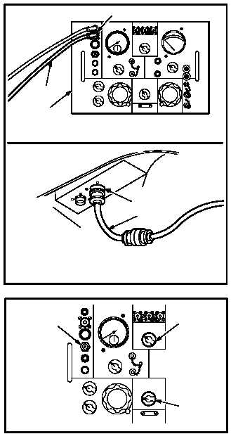
j. Attach harness adapter power cable (4) to
115V 400–cps power cable receptacle (5) on
indicator test set (6).
k. Attach adapter power cable (4) to ground ser-
vice utility receptacle (7) through access door
B60R.
CAUTION
Verify helicopter is clear for power ap-
plication.
l. Apply external electrical power (para 1.70).
10.135.4. Adapter Harness/Test Set Calibration
NOTE
When power is removed from test set,
reading displayed on CAPACITANCE IN-
DICATOR may not return to zero. No
damage will result to the test set.
a. Fuel Quantity Test Set (6) Calibration.
(1) Set test set power ON/OFF switch (1) to ON.
Allow test set (6) to warm up for FIVE MIN-
UTES.
(2) Set CAP-RES CHECK switch (8) to CAP
position.
(3) Set FUNCTION SELECTOR switch (9) to
CAP IND ZERO CAL.
(4) Set RANGE SELECTOR (10) to XI.
NOTE
Make all adjustments using insulated
screwdrivers.
(5) Check that CAPACITANCE INDICATOR (11)
reads 0 pF. If not, remove protective cap from
ZERO ADJ control (12), and adjust control
screw (13) until reading is exactly 0 pF.
GO TO NEXT PAGE
M04-3075-7
4
5
6
7
4
M04-3075-32
1
9
8
M04-3075-33
11
12
13
10


