TM 1-1520-238-23
11-706
11.160. CPG TO PILOT DIRECTIONAL F.S. 112.50 CONTROL BRACKET
REMOVAL/INSTALLATION – continued
11.160.6. Installation
NOTE
Install the longer bolts through the top
two mounting holes.
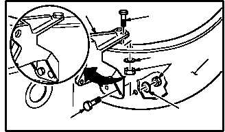
a. Install bracket (8) on airframe (14).
(1) Aline bracket (8) with holes on airframe (14).
(2) Install two bolts (18) through bracket (8) and
airframe (14).
(3) Install two bolts (17) through bracket (8) and
airframe (14).
(4) Install four washers (16) and nuts (15).
CAUTION
To prevent damage to flight control sys-
tem components, do not use force to
aline bellcrank with bracket or to aline
push-pull rod with bellcrank.
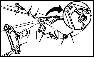
b. Install bellcrank (2) on bracket (8). Torque nut
(10) 30 to 40 INCH-POUNDS.
(1) Aline bellcrank (2) with bracket (8).
(2) Install bolt (11) through washer (12), bushing
(13), bracket (8), and bellcrank (2).
(3) Check fit of self-retaining bolt (11) (para 11.1).
(4) Install nut (10). Torque nut (10) to 30 INCH-
POUNDS. Use torque wrench.
(5) Increase torque to aline cotter pin hole, but do
not exceed 40 INCH-POUNDS.
(6) Install new cotter pin (9).
GO TO NEXT PAGE
15
17
18
16
8
M04-4328-6
16
14
2
9
8
12
13
M04-4328-7
11
10