TM 1-1520-238-23
11-780
Change 4
11.176. DIRECTIONAL MAGNETIC BRAKE REMOVAL/INSTALLATION – continued
11.176.6. Installation
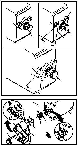
a. Establish midpoint (29) of shaft (28) travel.
(1) Rotate brake shaft (28) to full left stop (30)
and mark A.
(2) Rotate brake shaft (28) to full right stop (31)
and mark B.
(3) Measure and bisect dimension C.
(4) Mark midpoint (29) of shaft (28) travel.
b. Install -27 rig pin (32) in rig pin hole (33) in
bellcrank (34), and support (35). Use flight
control rigging kit.
c. Install magnetic brake (19) on floor (20).
(1) Install spacer rings (28.3), (28.2) and shim
(28.1) on shaft (28).
(2) Hold brake shaft (28) at midpoint (29).
(3) Position magnetic brake (19).
(4) Carefully insert brake shaft (28) in serrated
bore (36) of shaft (24).
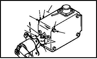
NOTE
Install laminated washers in same posi-
tion as removed.
(4) Install bolt (23) through washer (22) and shaft
(24).
(5) Install washer (22) and nut (21).
(6) Install four bolts (25) through outside washers
(26), magnetic brake (19), inside washers
(26), laminated washers (27), and floor (20).
GO TO NEXT PAGE
M04-3052-5
30
A
28
C
31
28
B
A
A
29
B
28
C
M04-3052-6A
19
28
24
36
35
34
33
32
20
28.1
28.3
28.2
M04-3052-7
27
19
20
26
25
22
21
23
26
24