TM 1-1520-238-23
Change 4
11-815
11.186. LATERAL MAGNETIC BRAKE MECHANISM ASSEMBLY REMOVAL/INSTALLATION – continued
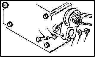
b. Remove brake mechanism assembly (5) from
magnetic brake shaft (6).
(1) Remove nut (7) and washer (8).
(2) Remove bolt (9) and washer (8).
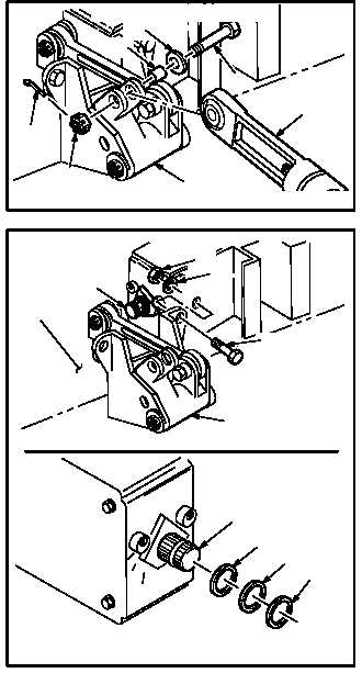
c. Remove feel spring cartridge (10) from brake
mechanism (5).
(1) Remove and discard cotter pin (11).
(2) Remove nut (12).
(3) Remove bolt (13), washer (14), and bushing
(15).
(4) Remove cartridge (10).
d. Remove brake mechanism (5) from airframe
(16).
(1) Remove four nuts (17) and washers (18).
(2) Remove four bolts (19).
(3) Slide brake mechanism (5) off shaft (6).
(4) Remove brake mechanism (5).
NOTE
Identify position of shim and spacer rings
for proper placement during installation.
(5) Remove shim (20), spacers (21) and (22)
from shaft (6).
(6) Retain shim (20) and spacers (21) and (22)
for installation.
GO TO NEXT PAGE
M04-4418-3
9
8
7
8
5
6
10
5
15
14
13
11
12
M04-4418-4
VIEW AFT BELOW PILOTS FLOOR
16
5
M04-4418-5
6
19
17
18
22
21
20
6


