TM 1-1520-238-23
11-936
11.216.
LINEAR VARIABLE DIFFERENTIAL TRANSDUCER (LVDT) ADJUSTMENT – continued
(3) To replace lateral servocylinder, go to para-
graph(s) 7.44 and 7.45.
(4) To replace directional servocylinder, go to
paragraphs(s) 7.32 and 7.33.
p. Check for null of less than 0.100 volt RMS at
the corresponding LVDT connector pins (para
11.217, Table 2-PLT or Table 3-CPG).
(1) If LVDT requires adjustment, go to step q.
(2) If no adjustment is necessary, go to step s.
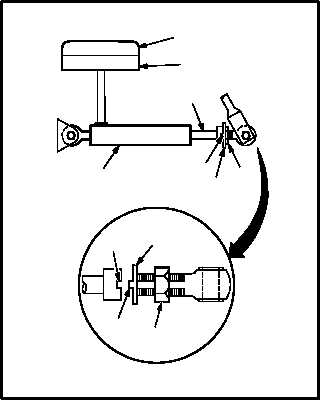
q. Adjust LVDT (20) to achieve null of approxi-
mate indication recorded in step h or k. Torque
nut (21) to 35 INCH-POUNDS.
(1) Remove lockwire from nut (21) on LVDT (20).
(2) Loosen nut (21) until keywasher (22) is clear
of LVDT rod end recess (23).
(3) Rotate LVDT rod (24) clockwise or counter-
clockwise until null approximates indication
recorded in step h or k.
(4) Null is not to exceed 0.100 volt RMS.
(5) Aline tab (25) of lockwasher (22) with LVDT
rod end recess (23).
(6) Torque nut (21) to 35 INCH-POUNDS. Use
torque wrench.
(7) Lockwire nut (21) to keywasher (22). Use
wire (item 222, App F).
r. Recheck null indication.
(1) If null indication exceeds 0.100 volt RMS,
repeat steps p. thru r.
GO TO NEXT PAGE
M04-3085-11
3
4
24
20
23
22
21
23
22
21
25