TM 1-1520-238-23
11-962
Change 3
11.224.
STABILATOR ACTUATOR REMOVAL/INSTALLATION – continued
11.224.6. Installation
NOTE
Actuator must be installed with mating
bolt heads up and aft. Receptacle
J995 to be up and J996 to be down.
Install attaching hardware so that bolt
head and washer are on inboard side.
Bushing may be on bolt head or nut
side, depending on actuator adjust-
ment.
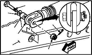
a. Install actuator (6) on airframe (16). Torque nut
(18) 95 to 110 INCH-POUNDS.
(1) Aline actuator (6) with airframe (16).
(2) Position bushing (21).
(3) Install bushing (21) through inboard side of
actuator (6).
(4) Install bolt (19) through washer (20), bushing
(21), inboard side of actuator (6), and air-
frame (16).
(5) Check fit of self-retaining bolt (19) (para
11.1).
(6) Install nut (18) on bolt (19). Torque nut (18) to
95 INCH-POUNDS. Use torque wrench.
(7) Increase torque to aline cotter pin hole, but do
not exceed 110 INCH-POUNDS.
(8) Install new cotter pin (17).
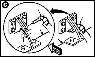
b. Remove -9 rig pin (15) from stabilator (5).
(1) One person support stabilator (5) on each
side.
(2) Remove -9 rig pin (15).
(3) Hold stabilator (5) horizontal.
GO TO NEXT PAGE
M04-2111-5
16
18
17
6
21
20
19
M04-2111-8
15
5
15
5