TM 1-1520-238-23
Change 3
11-963
11.224.
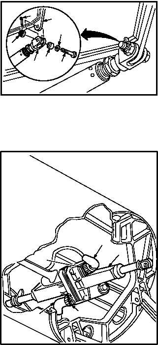
STABILATOR ACTUATOR REMOVAL/INSTALLATION – continued
NOTE
Install attaching hardware so that bolt
head and washer are on inboard side.
Bushing may be on bolt head or nut side,
depending on actuator adjustment.
c. Install actuator (6) on fitting (7). Torque nut (9)
95 to 110 INCH-POUNDS.
(1) Aline actuator (6) with fitting (7).
(2) Install bushing (12) in actuator (6).
(3) Install bolt (10) through washer (11) and
bushing (12) from inboard side of actuator
(6).
(4) Check fit of self-retaining bolt (10) (para
11.1).
(5) Install nut (9) on bolt (10). Torque nut (9) to 95
INCH-POUNDS. Use torque wrench.
(6) Increase torque to aline cotter pin hole, but do
not exceed 110 INCH-POUNDS.
(7) Install new cotter pin (8).
d. Attach connector P995 (1) to receptacle J995
(2).
e. Attach connector P996 (3) to receptacle J996
(4).
f. Inspect (QA).
g. Perform stabilator maintenance operational
check (TM 1-1520-238-T).
h. Install access covers L545 and R545 (para
2.2).
i. Perform a limited maintenance test flight for
the stabilator actuator (TM 1-1520-238-MTF).
END OF TASK
6
12
10
8
7
11
9
M04-2111-3
1
2
4
3
M04-2111-9
6