TM 1-1520-238-23
11-1006
Change 1
11.235.
PILOT DIRECTIONAL CONTROL PEDAL RELEASE SHAFT ASSEMBLY
REMOVAL/INSTALLATION – continued
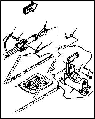
c. Remove pedal release handle (6) from pedal
support (7).
(1) Remove and discard cotter pin (8).
(2) Remove nut (9).
(3) Remove bolt (10) and washer (11) from han-
dle (6) and pedal support (7).
(4) Remove handle (6).
d. Remove shaft (12) from pedal adjust crank
(13).
(1) Remove and discard cotter pin (14).
(2) Remove nut (15).
(3) Remove bolt (16) and bushing (17) from
crank (13) and shaft (12).
(4) Remove shaft (12).
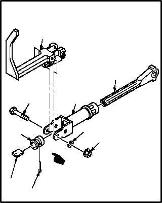
e. Remove handle (6) from pedal release nut
(18).
(1) Remove nut (19) and washer (20).
(2) Remove bolt (21) from handle (6).
(3) Remove handle (6).
f. Remove shaft (12) from release nut (18).
(1) Remove and discard cotter pin (22) from ped-
al adjust safety key (23).
(2) Remove key (23) and pedal rigging nut (24)
from shaft (12).
(3) Remove shaft (12).
GO TO NEXT PAGE
M04-4427-3
10
11
9
8
12
15
14
17
16
6
7
13
M04-4427-4A
21
20
19
12
18
23
22
24
6