TM 1-1520-238-23
11-1008
11.235.
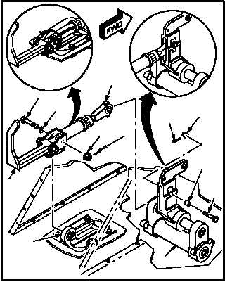
PILOT DIRECTIONAL CONTROL PEDAL RELEASE SHAFT ASSEMBLY
REMOVAL/INSTALLATION – continued
c. Install shaft (12) on crank (13).
(1) Aline shaft (12) with crank (13).
(2) Install bolt (16) and bushing (17) through
shaft (12) and crank (13).
(3) Check fit of self-retaining bolt (16) (para
11.1).
(4) Install nut (15).
(5) Install new cotter pin (14).
d. Install handle (6) on pedal support (7).
(1) Aline handle (6) with pedal support (7).
(2) Install bolt (10) through washer (11), handle
(6), and pedal support (7).
(3) Check fit of self-retaining bolt (10) (para
11.1).
(4) Install nut (9).
(5) Install new cotter pin (8).
e. Inspect (QA).
f. Perform directional flight control rigging
maintenance
operational
check
(TM 1-1520-238-T).
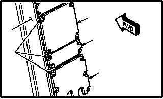
g. Install panels (1), (2), and (3) on console (4).
(1) Aline panels (1), (2), and (3) with console (4).
(2) Secure 14 fasteners (5) attaching panels (1),
(2), and (3) to console (4).
END OF TASK
M04-4427-6
10
11
9
8
12
15
14
17
16
6
7
13
M04-4427-7
3
2
1
5
4