TM 1-1520-238-23
11-1259
11.294.
RIGGING DIRECTIONAL FLIGHT CONTROLS BETWEEN PILOT PEDALS AND DIRECTIONAL
SERVOCYLINDER – continued
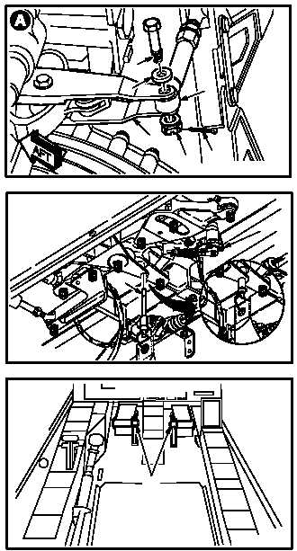
11.294.3. Rigging
a. Remove F.S. 542 rod end (1) from directional
servocylinder input linkage (2).
(1) Remove and discard cotter pin (3).
(2) Remove nut (4) from bolt (5).
(3) Remove bolt (5) and washer (6).
b. Enter pilot station (para 1.56). Observe all
safety precautions.
c. Apply external hydraulic power to aircraft
(para 1.72).
d. Observe pilot directional SPAD (7).
e. Slowly move pilot directional pedals (8) to
aline rig pin holes in SPAD (7).
f. Install -9 rig pin (9) in SPAD (7). Use flight
control rigging kit.
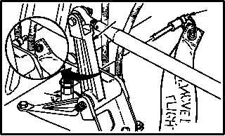
g. Install -9 rig pin (10) in directional F.S. 164
bellcrank (11). Use flight control rigging kit.
(1) If -9 rig pin (10) cannot be installed, adjust
upper end of F.S. 160 push-pull rod (12) to
aline rig pin holes (para 11.2).
(2) Install -9 rig pin (10).
GO TO NEXT PAGE
5
2
4
3
M04-3027-17
1
6
M04-3027-1
7
9
PILOT STATION
M04-3027-2
8
11
12
10
M04-3027-3