TM 1-1520-238-23
Change 1
11-1261
11.294.
RIGGING DIRECTIONAL FLIGHT CONTROLS BETWEEN PILOT PEDALS AND DIRECTIONAL
SERVOCYLINDER – continued
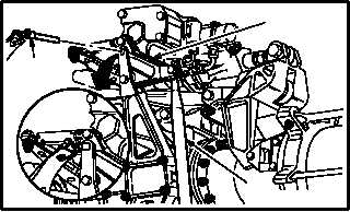
k. Install -9 rig pin (22) in directional F.S. 542
bellcrank (23). Use flight control rigging kit.
(1) If -9 rig pin (22) cannot be installed, adjust
lower end of F.S. 520 push-pull rod (24) to
aline rig pin holes (para 11.2).
(2) Install -9 rig pin (22).
NOTE
Rig pins installed must be a drop-fit con-
dition in holes. (A slight drag of rig pin is
acceptable.)
l. Verify drop fit of -5 rig pins (13), and -9 rig pins
(9), (10), (16), (19), and (22).
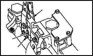
m. Slowly move directional servocylinder input
linkage (2) to aline lower lever (25) with upper
edge of boss (26) on servocylinder body.
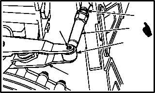
n. Check that holes (27) in input linkage (2) aline
with F.S. 542 rod end (1).
(1) If lever arm holes (27) do not aline with F.S.
542 rod end (1), adjust end of push pull rod
(28) rod end (28.1) to aline holes (27) (para
11.2).
(2) If holes (27) aline with rod end (1), go to next
step.
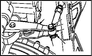
o. Install F.S. 542 rod end (1) on directional ser-
vocylinder input linkage (2). Torque nut (4) 30
to 40 INCH-POUNDS.
(1) Install bolt (5) through washer (6), input link-
age (2) and rod end (1).
(2) Check fit of self-retaining bolt (5) (para 11.1).
(3) Install nut (4). Torque nut (4) to 30 INCH-
POUNDS. Use torque wrench.
(4) Increase torque to aline cotter pin hole, but do
not exceed 40 INCH-POUNDS.
(5) Install new cotter pin (3).
GO TO NEXT PAGE
M04-3027-7
22
23
24
M04-3027-8
2
25
26
M04-3027-9A
28
1
2
27
28.1
2
4
3
6
M04-3027-18
1
5