TM 1-1520-238-23
11-1281
11.297.
SERVOCYLINDER ROD END ADJUSTMENT – continued
11.297.6. Adjust Directional Rod End
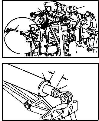
a. Install -9 rig pin (27) in directional F.S. 542
bellcrank (28). Use flight control rigging kit.
b. Measure and record distance between top of
directional servocylinder housing (29) and
bottom of locknut (30)
(1) This is measurement K. Use caliper.
c. Remove -9 rig pin (27) from directional F.S.
542 bellcrank (28).
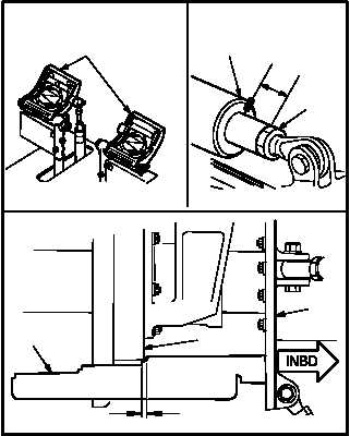
d. Install tool (31) between base (32) and hous-
ing (33). Use flight control rigging kit
(1) Check that tool (31) contacts base (32) and
alines with housing (33).
(2) Hold tool (31) firmly against base (32).
e. Move pilot directional pedals (34) to ensure
inboard edge of base (32) falls within mid ped-
al position limitations (35) specified on tool
(31).
f. Measure and record distance between top of
servocylinder housing (29) and bottom of
locknut (30).
(1) This is measurement L. Use caliper.
g. Remove tool (31) from base (32) and housing
(33).
GO TO NEXT PAGE
M04-3030-22
28
27
27
K
29
30
M04-3030-11
33
35
32
31
L
34
29
30
M04-3030-12


