TM 1-1520-238-23
11-1277
11.297.
SERVOCYLINDER ROD END ADJUSTMENT – continued
11.297.4. Adjust Longitudinal Servocylinder Rod End
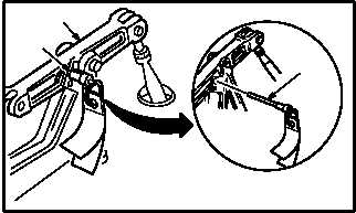
a. Install -9 rig pin (10) in longitudinal F.S. 165
bellcrank (11). Use flight control rigging kit.
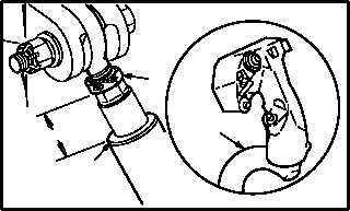
b. Measure and record distance between top of
longitudinal servocylinder housing (12) and
bottom of locknut (13).
(1) This is measurement D. Use caliper.
c. Remove -9 rig pin (10) from longitudinal F.S.
165 bellcrank (11).
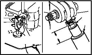
d. Move pilot cyclic stick (14) to aline BASIC DIM
pointer (para 11.288).
e. Measure and record distance between top of
housing (12) and bottom of locknut (13).
(1) This is measurement E. Use caliper.
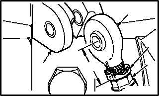
f. Remove servocylinder rod end (15) from lon-
gitudinal mixer bellcrank (16) (para 7.47).
g. Loosen lock nut (13).
(1) Remove lockwire.
h. Measure and record distance between top of
piston (17) and center of rod end (15).
(1) This is measurement F. Use caliper.
i. Adjust rod end (15) by turning in or out of
piston (17).
(1) If measurement D is larger than measure-
ment E, turn rod end (15) into piston (17).
Shorten measurement F an amount equal to
difference between measurements D and E.
(2) If measurement D is smaller than measure-
ment E, turn rod end (15) out of piston (17).
Lengthen measurement F an amount equal
to difference between measurements D and
E.
GO TO NEXT PAGE
M04-3030-18
10
11
10
M04-3030-4
14
12
13
D
13
E
12
M04-3030-5
BASIC DIM
POINTER
M04-3030-6
15
16
13
17
F