TM 1-1520-238-23
15-162
Change 3
15.42.
APU ENCLOSURE INSTALLATION - continued
NOTE
Ensure flame detector lens is pointing aft.
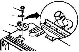
n. Install flame detector (29) on cover (26), if re-
moved.
(1) Position detector (29) on cover (26).
(2) Install two screws (30) through washers (31)
and detector (29) into cover (26).
o. Install APU controller (para 15.23).
p. Install APU time totalizing meter (para 15.24).
q. Attach connector P78 (32) to receptacle
(A10)J1 (33).
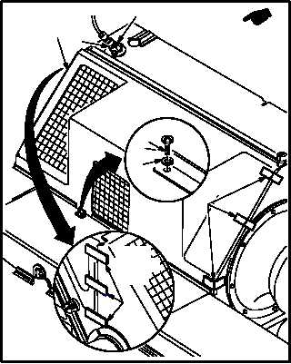
r. Install upper center cover (34).
(1) Position cover (34) on APU enclosure. Lock
six hook-and-pile fasteners (35).
s. Install four screws (36) through washers (37)
into cover (34).
t. Inspect (QA).
u. Secure access doors T250L, T250R, T290L,
T290R, and L325 (para 2.2).
v. Perform auxiliary power unit maintenance op-
erational check (TM 1-1520-238-T).
END OF TASK
30
26
29
31
M04-1531-10
32
35
35
37
36
34
33
M04-1531-13A
VIEW
LOOKING
AFT


