TM 1-1520-238-T-7
11–50
11–7.
SYSTEM DESCRIPTION (cont)
11–7
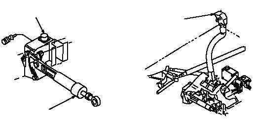
(d) The lateral feel spring and magnetic brake assembly (fig. 11–22) are located beneath the pilot’s
cyclic stick. The lateral magnetic brake assembly is a 28 VDC controlled unit that engages to establish a lateral
trim position. The feel trim assembly is a spring loaded device that overrides the lateral magnetic brake assembly
when the cyclic stick is moved against the magnetic brake assembly. The feel spring assembly allows cyclic stick
inputs to override the lateral force trim setting. When the cyclic stick is not engaged against the feel spring
assembly, lateral flight trim maintains current trim position.
M70-260
LATERAL
MAGNETIC BRAKE
FEEL SPRING
ASSEMBLY
CYCLIC
STICK
Figure 11–22.
Pilot Cyclic Control System Lateral Feel Spring and Magnetic Brake Assembly
(e) The lateral mechanical control linkage (fig. 11–23) provides an increase or decrease in cyclic
movement to the lateral servocylinder.
(f) The lateral servocylinder is hydraulically operated and connected to the mixer assembly. The lateral
servocylinder hydraulically assists the mechanical control linkage by moving the main rotor swashplate. The
swashplate moves pitch horns and blades of the main rotor head left or right. The mixer assembly lateral bellcrank
receives input motion from the lateral servocylinder and transmits lateral linear motion through two lateral links to
the stationary swashplate. An increase in left motion to the cyclic stick mechanical input causes the lateral
servocylinder to retract. Retraction of the lateral servocylinder pivots the lateral bellcrank downward while the left
lateral link moves up and the right lateral link moves down, tilting the nonrotating swashplate left. The nonrotating
swashplate transmits movement to the scissor assemblies. The scissor assemblies transmit rotational power to
the rotating swashplate. The rotating swashplate transmits the movement to the pitch link assemblies, changing
the pitch angle on the main rotor blades.
f. Directional Flight Control System.
(1) Purpose.
The purpose of the directional flight controls is to provide mechanical input to the tail rotor
assembly for directional heading and anti-torque control.
(2) System Operation.
(a) The pilot and CPG directional pedals (fig. 11–24) are moved forward or aft, providing a push-pull
action, to control directional movement of the helicopter.
(b) The directional LVDTs are located at the base of the pilot’s and CPG’s directional pedals. The pilot
and CPG directional LVDTs monitor pedal movement during DASEC, CAS and BUCS operation. An electrical
signal is developed proportional to pedal movement and sent to the directional servocylinder to position the tail
rotor.