TM 1-1520-238-10
2-49
2.37.8 Stabilator System.
A variable angle of inci-
dence stabilator is installed to enhance helicopter han-
dling characteristics. The stabilator is designed so that it
will automatically be positioned by stabilator control units.
These units determine stabilator position from airspeed,
pitch rate, and collective stick position inputs. Automatic
stabilator range of travel is from 5 trailing edge up
through 25 trailing edge down. Manual control is from 10
trailing edge up to 35 trailing edge down. The stabilator is
driven by two independent dc motors. Stabilator opera-
tion, in either manual or automatic mode, requires both ac
and dc power supplies. Associated crew station controls
and indicators are as follows:
a. Stabilator Circuit Breakers.
The stabilator re-
ceives 115 vac from the No. 1 essential ac bus through the
STAB MAN AC and STAB AUTO AC circuit breakers. It
also receives 28 vdc from the No. 1 essential dc bus
through the STAB MAN DC circuit breaker and from the
No. 3 essential dc bus through the STAB AUTO DC circuit
breaker. These circuit breakers are on the pilot overhead
circuit breaker panel.
b. Stabilator Manual Control Switch.
The stabila-
tor manual control switch is located on the stabilator con-
trol panel (fig 2-26) installed inboard and forward of the
friction grip on each collective stick. The switch, nose up
(NU), and nose down (ND), permits crewmembers to con-
trol the stabilator angle of incidence. The manual mode
will disengage both the normal auto and NOE/APRCH
modes below 80 KTAS. Selection of the manual mode will
cause the pilot and CPG MAN STAB caution lights to illu-
minate. Transitioning above 80 KTAS in the manual mode
will result in automatic switchover to auto mode. Failure of
the automatic switchover to auto mode will result in the fol-
lowing:
(1) Pilot and CPG MASTER CAUTION light starts
flashing.
(2) Pilot and CPG caution/warning MAN STAB
light starts flashing.
(3) Stabilator aural tone is heard.
Below 80 KTAS automatic mode is regained after selec-
tion of manual mode by momentarily pressing the auto-
matic operation/audio tone RESET button on either col-
lective stick.
c. NOE/APRCH Switch.
The NOE/APRCH switch,
located on the ASE control panel (fig 2-27), positions the
stabilator at 25 degrees (trailing edge down) below 80
KTAS. If auto mode is on, this mode is selectable at any
speed from a magnetically held switch. Transitioning past
80 knots will result in normal stabilator scheduling. Failure
to revert to normal stabilator scheduling will result in the
following:
(1) NOE/APRCH switch goes to OFF.
(2) Pilot and CPG MASTER CAUTION light starts
flashing.
(3) Pilot and CPG caution/warning MAN STAB
light starts flashing.
(4) Stabilator aural tone comes on.
Regaining auto mode after the NOE/APRCH mode is se-
lected is accomplished by momentarily pressing the auto-
matic operation/audio tone RESET button on either col-
lective stick or setting the NOE/APRCH switch to OFF.
Manual mode may be regained by selecting manual mode
with the NU/ND switch.
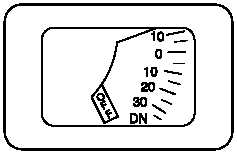
d. Stabilator Position Indicator.
The STAB POS
DEG indicator (fig 2-28), located in the upper right section
of the pilot and CPG instrument panels, provides a visual
indication of stabilator angle of incidence in either manual
or automatic modes of operation. It is calibrated from 10
trailing edge up to 35 trailing edge down to reflect the
position of the stabilator trailing edge. An OFF flag is dis-
played on the indicator face when the instrument is not op-
erating and dc electrical power is applied to the indicator.
With ac or dc power loss, both the OFF flag and pointer
are not displayed.
M01-311
POS
STAB
DEG
Figure 2-28.
Stabilator Position Indicator
e. Stabilator Placard.
A placard installed to the
right of the position indicator in each crew station lists sta-
bilator incidence angles for given airspeeds. Refer to
Chapter 5 for limitations.


