TM 1-1520-238-23
3-161
3.45.
TAIL LANDING GEAR TRAILING ARMS REMOVAL/INSTALLATION – continued
e. Check electrical connectors and receptacles
for distorted, burned, corroded, or bent con-
tacts. None allowed.
f. Check electrical connectors and receptacles
for cracks and damaged threads.
(1) No cracks allowed. Thread damage not to
exceed 50 percent of one thread.
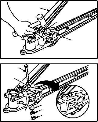
3.45.6. Installation
a. Install right trailing arm (35) on left trailing arm
and socket (36). Torque nut (38) to 35 INCH-
POUNDS.
(1) Aline mating holes for pin (42) in arm (35) with
arm and socket (36).
(2) Install pin (42) through mating holes of arm
(35) and arm and socket (36). Use mallet.
(3) Install pin cap (41) on bolt (37).
(4) Install bolt (37) with pin cap (41) through pin
(42), pin cap (40), and w9asher (39).
(5) Hold bolt (37). Install nut (38). Torque nut (38)
to 35 INCH-POUNDS. Use .
GO TO NEXT PAGE
M04-0038-10
36
42
35
.
40
39
38
42
41
37
.
M04-0038-11