TM 1-1520-238-23
3-162
3.45.
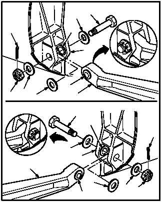
TAIL LANDING GEAR TRAILING ARMS REMOVAL/INSTALLATION – continued
NOTE
After proper installation the clearance
gap between the trailing arms and bush-
ings may allow the mounting bolts to be
rotated by finger pressure. This is a nor-
mal condition.
b. Install trailing arms (35) and (36) on pivot lugs
(27). Torque nuts (30) 135 to 150 INCH-
POUNDS.
(1) Aline trailing arms (35) and (36) with pivot
lugs (27).
(2) Support trailing arms (35) and (36) until two
bolts (29) are installed.
(3) Install two shims (34) between outboard
sides of trailing arms (35) and (36) and pivot
lugs (27). Remove laminates from shims (34)
to maintain 0.001 to 0.004 INCH gap be-
tween bushing (43) in trailing arms (35) and
(36), and bushing (44) in pivot lugs (27).
(4) Install two bolts (29) through washers (32),
pivot lug (27), trailing arms (35) and (36),
shim (34), and pivot lug (27).
(5) Hold two bolts (29). Install washers (31) and
nuts (30). Torque nuts (30) to 135 INCH-
POUNDS. Use torque wrench.
(6) Increase torque to aline cotter pin holes. Do
not exceed 150 INCH-POUNDS.
(7) Install two new cotter pins (28).
GO TO NEXT PAGE
28
44
32
29
27
34
36
43
30
31
M04-0038-12
29
32
44
27
28
30
31
34
35
43
LEFT SIDE
RIGHT SIDE